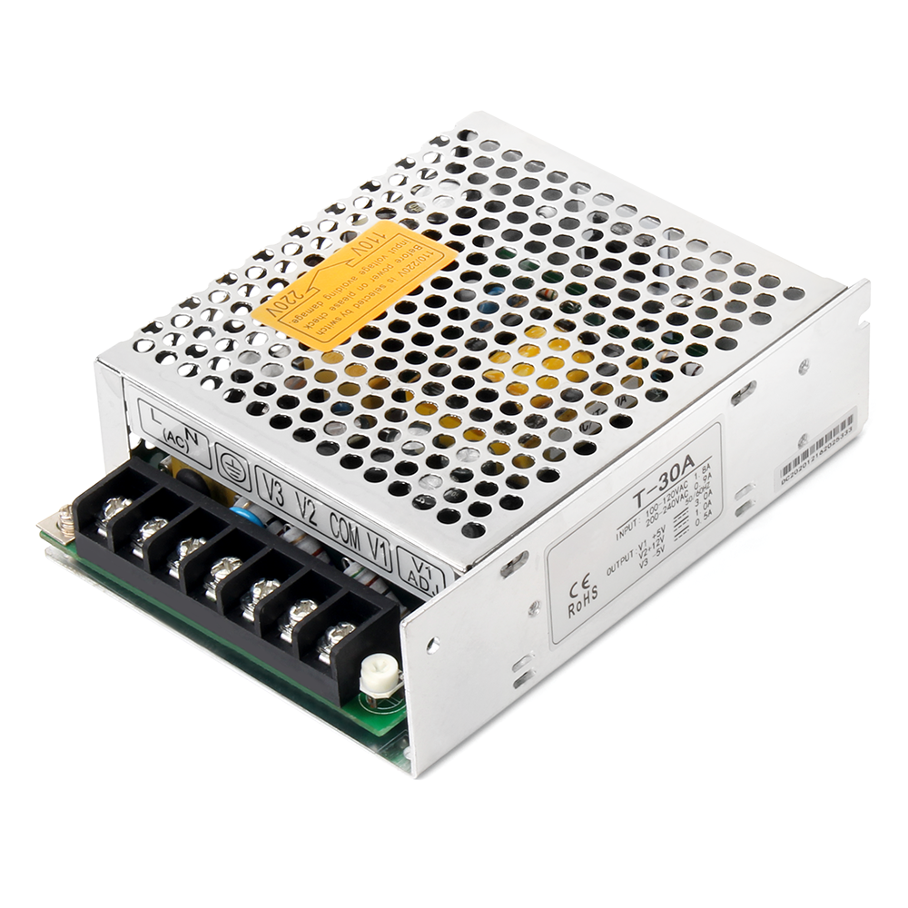
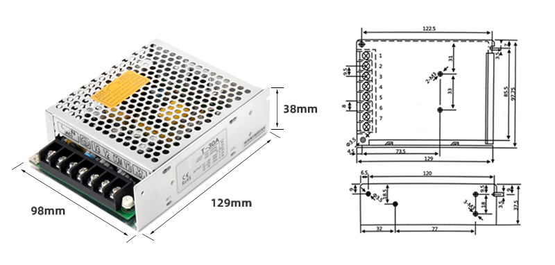
| Dimensional diagram of T-series switch power supply | |||||||||
| T-30
|
|||||||||
| T-series switch power supply parameter table | |||||||||
| model performance |
T-30A | T-30B | T-30C | ||||||
| CH1 | CH2 | CH3 | CH1 | CH2 | CH3 | CH1 | CH2 | CH3 | |
| DC output | 5V | 12V | -5V | 5V | 12V | -12V | 5V | 15V | -15V |
| output voltage tolerance | ±2% | 1.94 | 1.9 | 6% | ±2% | ±5% | ±2% | ±5% | ±5% |
| output current | 3A | 1A | 0.5A | 3A | 1A | 0.5A | 3A | 0.5A | 0.5A |
| Current range | 0.5-3A | 0.1-1A | 0.1-0.5A | 0.2-4A | 0.3-6A | 0.2-2.2A | 0.6-3A | 0.2-0.5A | 0.2-0.5A |
| Ripple and noise ① | 50MVP-P | 100mVp-p | 50MVP-P | 150MVP-P | 75mVp-p | 150mVp-p | 100MVP-P | 100mVp-p | 100mVp-p |
| Stability of incoming lines | ±0.5% | ±1% | ±1% | ±1% | ±0.5% | ±0.5% | ±0.5% | ±0.5% | ±0.5% |
| Load stability | ±0.5% | ±5% | ±5% | ±4% | ±0.5% | ±4% | ±1% | ±0.5% | ±0.5% |
| DC OUTPUT POWER | 30W | 33W | 30W | ||||||
| Efficiency (typical) ② | 72% | 72% | 83% | ||||||
| Adjustable range of DC voltage | CH:+10-5% | CH:+10-5% | CH:+10-5% | ||||||
| Input Voltage | 85-132VAC/170-264VAC switched by switch 240-370VDC 47-63Hz | ||||||||
| Input Current | 0.8A/115V 0.45A/230V | ||||||||
| Impulse current | Cold start current 18A/115VAC; 36A/230VAC | ||||||||
| Leakage current | <0.5mA240VAC | ||||||||
| overload protection | 105% to 150% cut off output, automatic recovery | ||||||||
| Overvoltage protection | CH1:5.75~6.75V | ||||||||
| temperature coefficient | ±0.03%℃(0~50℃) | ||||||||
| Start, rise, hold time | 200ms、50ms、30ms/230VAC | ||||||||
| Seismic resistance | 10-500Hz; 2G 10min/cycle, duration of 60 minutes, for each axis | ||||||||
| Pressure resistance | Input output interval: 3kV Input to shell interval: 1.5kV Output to shell interval: 0.5kVAC for one minute | ||||||||
| Isolation resistor | Between input and output, between input and housing, between output and housing: 500VDC/100M Ω | ||||||||
| Working temperature and humidity | -10℃~+60℃ 20%~90%RH | ||||||||
| Storage temperature and humidity | -20℃~+60℃ | ||||||||
| External dimensions | 129*98*38mm | ||||||||
| weight | 0.4kg | ||||||||
| safety standards | Meets UL1950 requirements (does not apply for labeling) | ||||||||
| EMC standards | DESIGN REFER TO FCC PART15 CLASS A | ||||||||
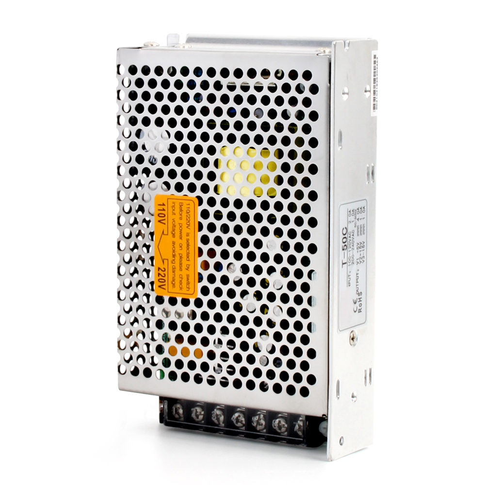
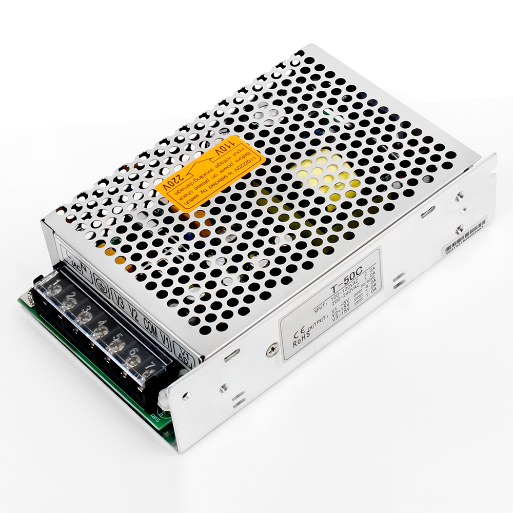
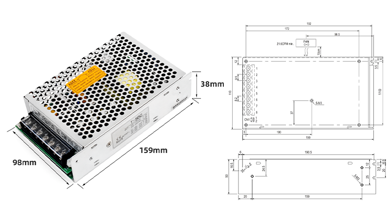
| Dimensional diagram of T-series switch power supply | ||||||||||||
| T-50
|
||||||||||||
| model performance |
T-50A | T-50B | T-50C | T-50D | ||||||||
| CH1 | CH2 | CH3 | CH1 | CH2 | CH3 | CH1 | CH2 | CH3 | CH1 | CH2 | CH3 | |
| DC output | 5V | 12V | -5V | 5V | 12V | -12V | 5V | 15V | -15V | 5V | 12V | 24V |
| output voltage tolerance | ±2% | ±5% | ±5% | ±2% | ±5% | ±5%% | ±2% | ±5% | ±5% | ±2% | ±6% | ±6% |
| output current | 7A | 1A | 1A | 5A | 1A | 1A | 4A | 1A | 1A | 4A | 1A | 1A |
| Current range | 2-7A | 0.2-1A | 0.2-1A | 1-5A | 0.2-1A | 0.2-1A | 1-4A | 0.2-1A | 0.2-1A | 1-4A | 0.2-1A | 0.2-1A |
| Ripple and noise ① | 100MV | 100mV | 50MV | 150MV | 75mV | 150mV | 100MV | 100mV | 100mV | 100MV | 75mV | 75mV |
| Stability of incoming lines | ±0.5% | ±1% | ±1% | ±1% | ±0.5% | ±0.5% | ±0.5% | ±0.5% | ±0.5% | ±0.5% | ±0.5% | ±0.5% |
| Load stability | ±0.5% | ±5% | ±5% | ±4% | ±0.5% | ±4% | ±1% | ±0.5% | ±0.5% | ±1% | ±0.5% | ±0.5% |
| DC OUTPUT POWER | 50W | 49W | 50W | 51W | ||||||||
| Efficiency (typical) ② | 66% | 69% | 71% | 72% | ||||||||
| Adjustable range of DC voltage | CH:+10-5% | CH:+10-5% | CH:+10-5% | CH1:+10-5% | ||||||||
| Input Voltage | 85-132VAC/170-264VAC switched by switch 240-370VDC 47-63Hz | |||||||||||
| Input Current | 1.6A/115V 0.8A/230V | |||||||||||
| Impulse current | Cold start current 20A/115VAC; 40A/230VAC | |||||||||||
| Leakage current | <0.5mA240VAC | |||||||||||
| overload protection | 105% to 135% cut off output, automatic recovery | |||||||||||
| Overvoltage protection | CH1:5.75~6.75V | |||||||||||
| temperature coefficient | ±0.03%℃(0~50℃) | |||||||||||
| Start, rise, hold time | 200ms, 50ms, 16ms | |||||||||||
| Seismic resistance | 10~500Hz; 2G 10min/cycle, duration of 60 minutes, for each axis | |||||||||||
| Pressure resistance | Input output interval: 1.5kV Input to shell interval: 1.5kV Output to shell interval: 0.5kVAC for one minute | |||||||||||
| Isolation resistor | Between input and output, between input and housing, between output and housing: 500VDC/100M Ω | |||||||||||
| Working temperature and humidity | -10℃~+60℃ 20%~90%RH | |||||||||||
| Storage temperature and humidity | -20℃~+85℃ 10%~95%RH | |||||||||||
| External dimensions | 159*98*38mm | |||||||||||
| weight | 0.54kg | |||||||||||
| safety standards | Meets UL1950 requirements (does not apply for labeling) | |||||||||||
| EMC standards | DESIGN REFER TO FCC PART15 CLASS A | |||||||||||
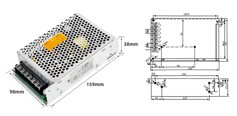
| Dimensional diagram of T-series switch power supply | ||||||||||||
| T-60
|
||||||||||||
| model performance |
T-60A | T-60B | T-60C | T-60D | ||||||||
| CH1 | CH2 | CH3 | CH1 | CH2 | CH3 | CH1 | CH2 | CH3 | CH1 | CH2 | CH3 | |
| DC output | 5V | 12V | -5V | 5V | 12V | -12V | 5V | 15V | -15V | 5V | 12V | 24V |
| output voltage tolerance | ±2% | ±5% | ±5% | ±2% | ±5% | ±5%% | ±2% | ±5% | ±5% | ±2% | ±6% | ±6% |
| output current | 7A | 2A | 1A | 6A | 2A | 1A | 5A | 2A | 0.5A | 5A | 1A | 1A |
| Current range | 1-7A | 0.2-2A | 0.2-1A | 1-6A | 0.2-2A | 0.2-1A | 1-5A | 0.2-2A | 0-0.5A | 0.6-5A | 0.2-1A | 0.2-1A |
| Ripple and noise ① | 100MV | 100mV | 50MV | 150MV | 75mV | 150mV | 100MV | 100mV | 100mV | 100MV | 75mV | 75mV |
| Stability of incoming lines | ±0.5% | ±1% | ±1% | ±1% | ±0.5% | ±0.5% | ±0.5% | ±0.5% | ±0.5% | ±0.5% | ±0.5% | ±0.5% |
| Load stability | ±0.5% | ±5% | ±5% | ±4% | ±0.5% | ±4% | ±1% | ±0.5% | ±0.5% | ±1% | ±0.5% | ±0.5% |
| DC OUTPUT POWER | 64W | 65W | 67.5W | 61W | ||||||||
| Efficiency (typical) ② | 66% | 69% | 71% | 72% | ||||||||
| Adjustable range of DC voltage | CH:+10-5% | CH:+10-5% | CH:+10-5% | CH1:+10-5% | ||||||||
| Input Voltage | 85-132VAC/170-264VAC switched by switch 240-370VDC 47-63Hz | |||||||||||
| Input Current | 1.6A/115V 0.8A/230V | |||||||||||
| Impulse current | Cold start current 20A/115VAC; 40A/230VAC | |||||||||||
| Leakage current | <0.5mA240VAC | |||||||||||
| overload protection | 105% to 135% cut off output, automatic recovery | |||||||||||
| Overvoltage protection | CH1:5.75~6.75V | |||||||||||
| temperature coefficient | ±0.03%℃(0~50℃) | |||||||||||
| Start, rise, hold time | 200ms, 50ms, 16ms | |||||||||||
| Seismic resistance | 10~500Hz; 2G 10min/cycle, duration of 60 minutes, for each axis | |||||||||||
| Pressure resistance | Input output interval: 1.5kV Input to shell interval: 1.5kV Output to shell interval: 0.5kVAC for one minute | |||||||||||
| Isolation resistor | Between input and output, between input and housing, between output and housing: 500VDC/100M Ω | |||||||||||
| Working temperature and humidity | -10℃~+60℃ 20%~90%RH | |||||||||||
| Storage temperature and humidity | -20℃~+85℃ 10%~95%RH | |||||||||||
| External dimensions | 159*98*38mm | |||||||||||
| weight | 0.54kg | |||||||||||
| safety standards | Meets UL1950 requirements (does not apply for labeling) | |||||||||||
| EMC standards | DESIGN REFER TO FCC PART15 CLASS A | |||||||||||
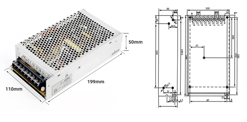
| Dimensional diagram of T-series switch power supply | ||||||||||||
| T-120
|
||||||||||||
| model performance |
T-120A | T-120B | T-120C | T-120D | ||||||||
| CH1 | CH2 | CH3 | CH1 | CH2 | CH3 | CH1 | CH2 | CH3 | CH1 | CH2 | CH3 | |
| DC output | 5V | 12V | -5V | 5V | 12V | -12V | 5V | 15V | -15V | 5V | 12V | 24V |
| output voltage tolerance | ±2% | ±5% | ±5% | ±2% | ±5% | ±5%% | ±2% | ±5% | ±5% | ±2% | ±6% | ±6% |
| output current | 11A | 5A | 1A | 11A | 4.5A | 1A | 5A | 2.5A | 1A | 6A | 2A | 2A |
| Current range | 2-11A | 0.5-5A | 0.2-1A | 2-11A | 0.5-4.5A | 0.2-1A | 2-10A | 0.2-1A | 0.2-1A | 0.6-4A | 0.2-1.2A | 0.2-1.2A |
| Ripple and noise ① | 100MV | 150mV | 150mV | 80MV | 150mV | 150mV | 80MV | 150mV | 150mV | 80MV | 120mV | 180mV |
| Stability of incoming lines | ±0.5% | ±1% | ±1% | ±0.5% | ±1% | ±1% | ±0.5% | ±1% | ±1% | ±0.5% | ±1% | ±1% |
| Load stability | ±1% | ±5% | ±5% | ±1% | ±5% | ±5% | ±1% | ±5% | ±5% | ±1% | ±5% | ±5% |
| DC OUTPUT POWER | 120W | 120W | 120W | 120W | ||||||||
| Efficiency (typical) ② | 77% | 77% | 76% | 80% | ||||||||
| Adjustable range of DC voltage | CH:+10-5% | CH:+10-5% | CH:+10-5% | CH1:+10-5% | ||||||||
| Input Voltage | 90-132VAC/170-264VAC switched by switch 240-370VDC 47-63Hz | |||||||||||
| Input Current | 2.5A/115V 1.25A/230V | |||||||||||
| Impulse current | Cold start current 30A/115VAC; 60A/230VAC | |||||||||||
| Leakage current | <0.5mA240VAC | |||||||||||
| overload protection | 105% to 135% cut off output, automatic recovery | |||||||||||
| Overvoltage protection | CH1:5.75~6.75V | |||||||||||
| temperature coefficient | ±0.03%℃(0~50℃) | |||||||||||
| Start, rise, hold time | 200ms, 50ms, 16ms | |||||||||||
| Seismic resistance | 10~500Hz; 2G 10min/cycle, duration of 60 minutes, for each axis | |||||||||||
| Pressure resistance | Input output interval: 1.5kV Input to shell interval: 1.5kV Output to shell interval: 0.5kVAC for one minute | |||||||||||
| Isolation resistor | Between input and output, between input and housing, between output and housing: 500VDC/100M Ω | |||||||||||
| Working temperature and humidity | -10℃~+60℃ 20%~90%RH | |||||||||||
| Storage temperature and humidity | -20℃~+85℃ 10%~95%RH | |||||||||||
| External dimensions | 199*110*50mm | |||||||||||
| weight | 0.9kg | |||||||||||
| safety standards | Meets UL1950 requirements (does not apply for labeling) | |||||||||||
| EMC standards | DESIGN REFER TO FCC PART15 CLASS A | |||||||||||



Reviews
There are no reviews yet.